How Do Mechanical Pressure Switches Work?
Mechanical pressure switches are classic industrial instruments that do not rely on complex electronic circuits. Instead, they achieve signal conversion by balancing physical forces. Their compact structure, stable response, and high overload capacity make them essential for hydraulic systems, lubrication equipment, and industrial automation.
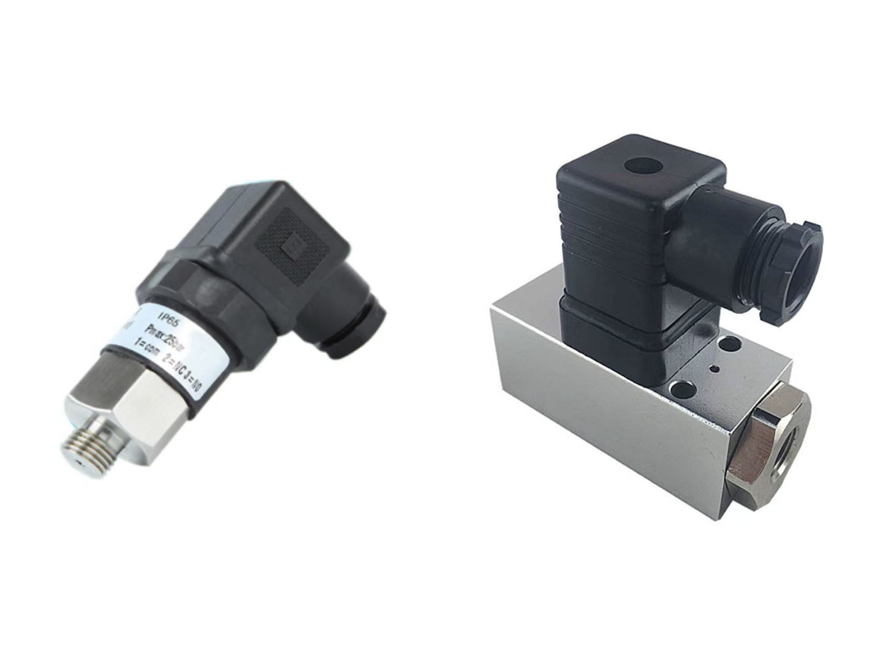
As a professional supplier of industrial instrumentation, ZINACA provides this detailed look into the core mechanisms of compact mechanical pressure switches.
The Core Principle: Force Balance Mechanism
The operation of a mechanical pressure switch is built on the balance between two opposing forces: the process pressure and the preloaded spring force.
The Battle of Forces:
Process Pressure: The measuring element (piston or diaphragm) comes into direct contact with the system medium. As system pressure rises, it exerts an upward force on this element.
Preloaded Spring Force: An internal precision spring generates a downward counter-force. By adjusting the setting screw at the top, the spring's compression is changed.
Signal Triggering: When the process pressure overcomes the preset spring resistance, the internal piston (for high pressure) or diaphragm (for low pressure) shifts. This minute mechanical movement triggers a preset mechanism—typically a microswitch—converting physical pressure into an electrical signal output, such as Normally Open (NO) or Normally Closed (NC).
Design Variations for Different Pressures
To ensure sensitivity and stability across various ranges, mechanical pressure switches use different sensing elements:
Diaphragm Type: Used for low-pressure applications. Because the diaphragm has a large surface area, even small pressure changes generate enough force to overcome the spring tension.
Piston Type: Used for high-pressure applications, such as ZINACA's 400 bar series. The smaller surface area of the piston allows it to withstand extreme system shocks, with overload capacities reaching up to 1230 bar.
Key Features of Compact Pressure Switches
These switches are engineered for environments with limited space and harsh conditions:
Flexible Adjustment: The switching point is set by turning the adjustment screw. The deeper the screw is turned, the higher the spring preload, and the higher the pressure required to trigger the switch.
Superior Electrical Performance: Features gold-plated contacts for high contact capacity and excellent conductivity, supporting both NO and NC signals.
Standardized Wiring: Uses a DIN-standard plug for easy, reliable wiring with high protection ratings.
Extreme Durability: High repeatability and a massive overload capacity ensure long-term stability in systems with frequent pressure fluctuations.
Installation Best Practices
Range Verification: Before installation, confirm that the system's maximum pressure does not exceed the switch's rated range.
Thread Matching: Ensure the connection port threads (e.g., G1/4 or NPT) match perfectly to avoid damaging the product.
Protection: During installation, protect the wiring plug and the bottom probe. Avoid any strong impacts.
Clean Sealing: Ensure the measuring point and sealing surfaces are clean. Use appropriate torque tools to tighten the switch to prevent leaks or housing deformation.
The mechanical pressure switch remains an indispensable safety component due to its simplicity and reliability. Whether providing overpressure protection for hydraulic stations or controlling the automatic start-stop of water systems, it offers precise mechanical feedback.