How to Calibrate a Pressure Transmitter: A Professional Technical Guide
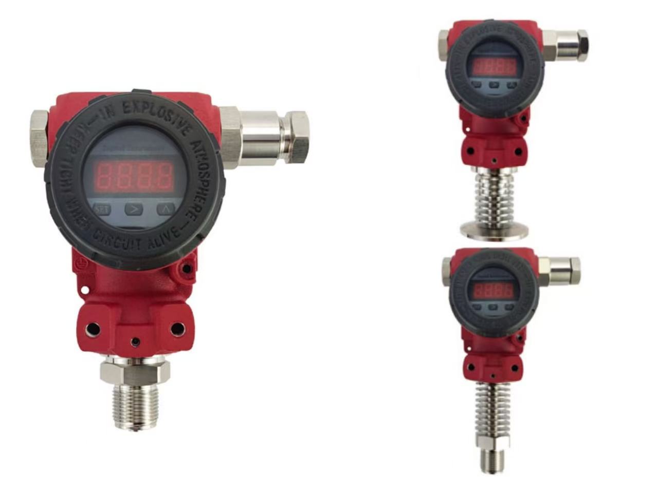
The Pressure Transmitter is a cornerstone of modern industrial regulation, converting physical pressure from gases or liquids into standard electrical signals (such as 4-20mA DC). These signals allow secondary instruments—like alarms, recorders, and regulators—to perform precise measurements and process adjustments.
Over time, environmental factors and mechanical wear can cause measurement deviations. To maintain system integrity, periodic calibration is essential. Below is the professional procedure for calibrating both conventional and intelligent pressure transmitters.
1. Pre-Calibration Preparation
Before starting the calibration, you must ensure the environment is safe and the equipment is properly isolated. For differential pressure transmitters, the process can often be performed on-site without removing the impulse lines:
Isolation: Close both the high-pressure and low-pressure valves on the three-valve manifold. Open the balance valve.
Venting: Loosen the exhaust/drain valves or plugs to vent the pressure chambers to the atmosphere.
Connection: Connect the pressure source (hand pump or standard pressure generator) to the positive pressure side using a high-quality flexible hose. Ensure the negative pressure side remains open to the atmosphere.
Circuit Setup: Connect an ammeter (or voltmeter) and a handheld communicator (HART) to the transmitter's output loop.
Warm-up: Power on the device and allow it to pre-heat to ensure electronic stability before checking for air leaks in the connections.
2. Calibrating Conventional Pressure Transmitters
Conventional transmitters rely on analog adjustments. The goal is to reach a linear relationship between input pressure and output current.
Zero Adjustment: With no pressure applied, adjust the zero screw until the output is exactly 4mA.
Span (Range) Adjustment: Apply the full-scale pressure and adjust the span screw until the output is 20mA.
The Iterative Process: Because adjusting the span can slightly shift the zero point, you must repeat these steps.
Quick Tip: If the zero point shifts significantly, adjust the span to about 1/5th of the required correction and then re-zero. This "fast adjustment" method helps reach the 4-20mA balance more efficiently.
3. Calibrating Intelligent (HART) Pressure Transmitters
Calibrating a smart transmitter—such as those manufactured by ZINACA Instruments or ABB—requires a different approach. Because smart transmitters involve a microprocessor and D/A (Digital-to-Analog) converters, simply turning a screw is not enough. The process involves "Re-ranging," "Trimming," and "Setting."
Step 1: 4-20mA Micro-adjustment (D/A Trim)This step calibrates the internal D/A converter. It does not require an external pressure source. It ensures that the digital value calculated by the microprocessor matches the actual analog current output.
Step 2: Full-Scale Micro-adjustment (Sensor Trim)This step matches the digital reading of the sensor to the actual applied pressure. You must apply a precise, known pressure from a standard source so the transmitter can "learn" what a true 0% and 100% pressure looks like.
Step 3: Re-ranging (Output Mapping)This final step links the analog 4-20mA output to the calibrated pressure range. This is equivalent to using the external Zero (Z) and Range (R) buttons on the transmitter housing, ensuring the 4mA and 20mA points correspond exactly to your required process limits.
Why Choose ZINACA for Your Pressure Needs?
At ZINACA Instruments, we specialize in high-precision, intelligent measurement solutions. Our transmitters feature:
HART Protocol Compatibility: Simplifies the three-step calibration process described above.
High-Stability Monocrystalline Silicon Sensors: Reduce the frequency of calibration by minimizing zero drift.
User-Friendly Interface: Backlit LCDs and easy-to-access adjustment points for faster on-site maintenance.