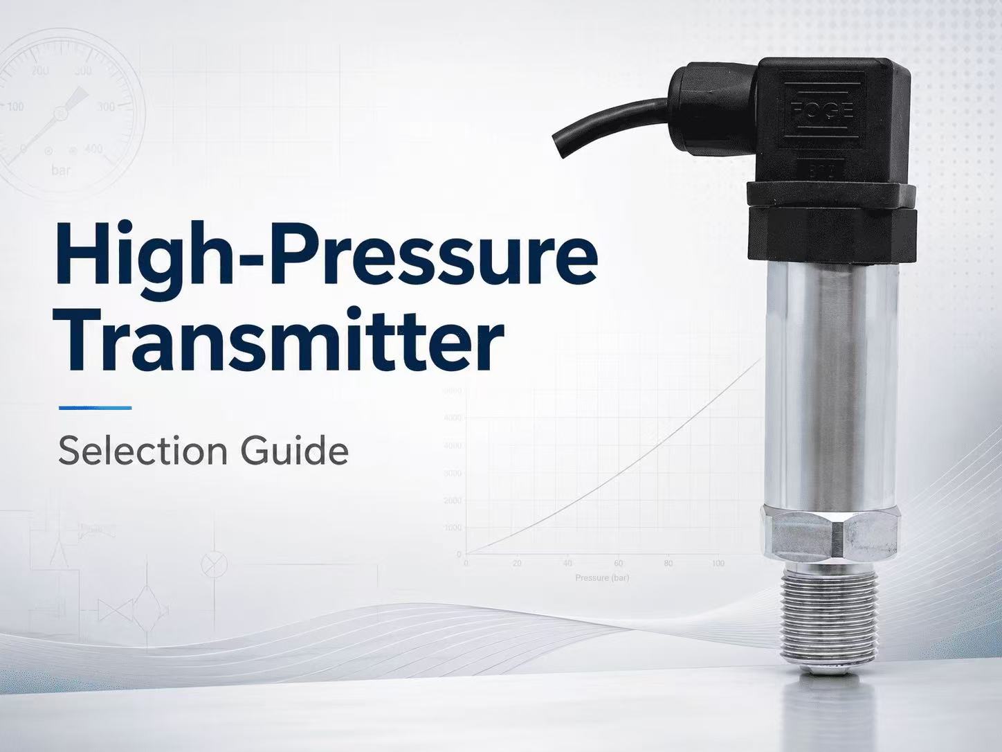
High-Pressure Transmitter Selection Guide: 7 Key Factors for Reliable Measurement
Selecting ahigh-pressure transmitter involves more than choosing a measuring range from a datasheet. In hydraulic systems, high-pressure pumps, waterjet equipment, pressure test benches, and intensifier systems, the transmitter may be exposed to pressure peaks, rapid pressure cycles, mechanical shock, vibration, and demanding sealing conditions.
A transmitter that matches the normal operating pressure may still fail prematurely if the maximum pressure peak, pulsation frequency, process connection, medium temperature, or electrical interface has not been considered.
This high-pressure transmitter selection guide explains seven key factors that engineers, equipment manufacturers, and procurement teams should evaluate before selecting a transmitter for high-pressure or ultra-high-pressure measurement.
Quick High-Pressure Transmitter Selection Checklist
Before requesting a quotation or confirming a model, collect the following information:
| Selection Item | Information Required |
|---|---|
| Normal working pressure | Continuous operating pressure |
| Maximum pressure peak | Highest expected transient pressure |
| Pressure cycle | Pulsation frequency and operating cycles |
| Measuring range | Required calibrated range and pressure unit |
| Accuracy | Required percentage of full scale |
| Output signal | 4–20 mA, 0–5 V, or 0–10 V |
| Power supply | Available DC supply voltage |
| Process connection | Thread, cone-seat geometry, and pressure rating |
| Medium | Hydraulic oil, water, or another compatible liquid |
| Temperature | Medium and ambient temperature |
| Electrical connection | Aviation connector, DIN connector, or cable outlet |
| Installation | Available space, vibration, shock, and ingress protection |
Providing complete application data reduces the risk of selecting an unsuitable pressure range or connection.
1. Determine the Normal Working Pressure and Maximum Pressure Peak
The first step is to distinguish between normal working pressure and maximum pressure peak.
Normal working pressure is the pressure the system maintains during regular operation. Peak pressure is the highest transient pressure that may occur during pump startup, valve switching, rapid load changes, hydraulic impact, or system shutdown.
A transmitter should not be selected only according to normal pressure. For example, a hydraulic system may normally operate at 300 MPa but generate substantially higher short-duration pressure peaks. These peaks can affect the sensing element even when they are too brief to appear clearly on a standard display.
ZINACA cone-sealed high-pressure transmitters are available in standard ranges including:
0–150 MPa
0–250 MPa
0–300 MPa
0–350 MPa
0–400 MPa
0–450 MPa
0–500 MPa
Customized measuring ranges are available up to 0–1000 MPa.
For applications operating continuously near the full-scale limit, selecting a higher calibrated range may help improve service life. However, increasing the range also reduces measurement resolution at lower pressures. The final range should therefore balance pressure protection with the required measurement sensitivity.
When selecting the range, always provide:
Normal operating pressure
Maximum pressure peak
Required pressure unit
Duration of the pressure peak
Expected measurement resolution
2. Evaluate Pressure Pulsation, Overload, and Cycle Life
High-pressure pumps, intensifiers, hydraulic presses, and reciprocating equipment rarely produce perfectly stable pressure. Their output may contain repetitive pulsation, rapid pressure fluctuations, or mechanical impact.
These dynamic conditions can be more demanding than a steady pressure of the same value.
For pulsating applications, the supplier should be informed of:
Pressure-cycle frequency
Pressure variation during each cycle
Startup and shutdown conditions
Expected operating hours
Frequency of maximum-pressure events
The ZINACA ultra-high-pressure transmitter design has a minimum overload pressure of two times the rated pressure and a minimum burst pressure of five times the rated pressure. Its specified pressure-cycle life is up to 10 million cycles from zero to full scale.
Overload and burst ratings should not be treated as normal operating ranges. They are safety and durability parameters, not recommended continuous working pressures.
When a system contains severe pulsation, the complete installation should also be reviewed. Pipe arrangement, pressure ports, valves, impulse passages, and mechanical mounting can all affect the pressure transmitted to the sensing element.
3. Select the Required Accuracy and Long-Term Stability
Higher accuracy is not automatically necessary for every high-pressure application.
The correct accuracy depends on how the measurement will be used:
General equipment monitoring
Pump control
Hydraulic system protection
Process control
Test bench data acquisition
Calibration or performance testing
Available accuracy options for the ZINACA high-pressure transmitter include:
±0.25% FS
±0.5% FS
±1.0% FS
For equipment monitoring and general hydraulic control, ±0.5% FS or ±1.0% FS may be sufficient. Test benches, research equipment, and detailed performance analysis may require ±0.25% FS.
Full-scale accuracy should also be considered together with the selected pressure range. For example, the absolute error represented by 0.5% FS will be greater on a 500 MPa transmitter than on a 150 MPa transmitter.
Long-term stability is another important factor. The specified long-term stability of the ZINACA design is no more than 0.1% FS per year. Stable output helps reduce measurement drift and the frequency of recalibration, especially in equipment that operates continuously.
4. Confirm the Process Connection and Cone-Seat Geometry
The process connection is one of the most critical parts of an ultra-high-pressure measurement system.
Standard low-pressure threaded connections may rely on gaskets, O-rings, sealing tape, or thread interference. At ultra-high pressure, the sealing structure must be designed specifically for the pressure level and the mechanical load.
A cone-sealed process connection uses a matched metal-to-metal sealing surface. When the male and female cone geometry is correct, the connection provides a dependable sealing interface for high-pressure liquid systems.
Available ZINACA process connection options include:
M20 × 1.5 cone-sealed male thread
M22 × 1.5 cone-sealed male thread
Customized thread and cone-seat dimensions
The thread specification alone is not enough. Two connections may have the same thread size but different cone angles, sealing diameters, internal passages, or seating depths.
Before ordering, confirm:
Thread type and pitch
Male or female connection
Cone angle
Cone-seat diameter
Sealing depth
Pressure rating of the mating connection
Installation drawing or sample dimensions
The mating female connection must use the correct cone-seat geometry and have an equal or higher pressure rating than the transmitter connection.
Using an incorrectly matched cone seat may lead to poor sealing, installation damage, unstable measurement, or leakage.
5. Match the Output Signal, Power Supply, and Control System
The transmitter output must be compatible with the PLC, data acquisition system, controller, display, or test equipment receiving the signal.
Common output options include:
4–20 mA, Two-Wire
A 4–20 mA output is widely used in industrial control systems. It is suitable for longer cable distances and environments where electrical interference may be present.
The standard transmitter power supply is 24 VDC nominal, with a typical supply range of 9–36 VDC depending on configuration. The maximum load resistance for the current-output version is 800 Ω.
0–5 V or 0–10 V, Three-Wire
Voltage outputs are commonly used with test equipment, embedded control systems, local data acquisition devices, and shorter cable runs.
For voltage-output versions, the receiving input should have a minimum load resistance of 50 kΩ.
Before selecting the electrical version, confirm:
Required output signal
Available power supply
PLC or controller input type
Cable length
Load resistance
Grounding arrangement
Required response characteristics
The output, power supply, and wiring method should be confirmed as one complete configuration rather than selected independently.
6. Check Medium and Temperature Compatibility
The process medium directly contacts the pressure-sensing structure and process connection. Material compatibility must therefore be confirmed before installation.
The ZINACA cone-sealed transmitter uses an integral sensing structure with special-alloy pressure-bearing components. It is designed primarily for demanding liquid-pressure applications such as hydraulic oil, water, and compatible industrial fluids.
The standard specified medium and ambient temperature range is:
Medium temperature: −20 to +85°C
Ambient temperature: −20 to +85°C
Before selection, provide the exact medium rather than describing it only as “liquid.” Important information may include:
Chemical composition
Concentration
Viscosity
Operating temperature
Presence of particles
Lubricating properties
Corrosiveness
Possibility of crystallization or solidification
A material suitable for hydraulic oil may not automatically be suitable for an aggressive chemical solution. For corrosive or unusual media, compatibility should be reviewed separately by the manufacturer.
Temperature also affects transmitter electronics, seals, cable materials, and measurement stability. Applications outside the standard temperature range should be confirmed before production.
7. Review Environmental and Installation Conditions
High-pressure transmitters are often installed directly on pumps, hydraulic manifolds, mobile equipment, presses, and test systems. These locations may expose the transmitter to vibration, mechanical shock, moisture, dust, and limited installation space.
Important environmental specifications of the ZINACA transmitter include:
IP65 enclosure protection
Vibration resistance up to ±20 g
Shock resistance of 100 g for 11 ms
Output change below 0.1% FS within a 20–1000 Hz mechanical vibration range
Available electrical connection options include:
Four-pin aviation connector
DIN 43650/Hirschmann connector
Direct cable outlet
An aviation connector offers a compact interface for industrial equipment. A DIN connector can simplify field wiring and maintenance. A cable outlet may be preferable where the connection must be sealed or where installation space is restricted.
Installation planning should also consider:
Available mounting clearance
Connector orientation
Cable bending radius
Access for tightening tools
Protection from direct mechanical impact
Electrical grounding
Water and dust exposure
Accessibility for calibration and replacement
The final production drawing should be approved when dimensional limitations are critical.
Typical Applications of Ultra-High-Pressure Transmitters
Cone-sealed ultra-high-pressure transmitters are commonly used in:
Ultra-high-pressure hydraulic systems
Hydraulic presses
High-pressure pumps
Waterjet cutting equipment
Waterjet cleaning systems
Pressure test benches
Hydrostatic test systems
Intensifier systems
Pressure-boosting equipment
Industrial high-pressure cleaning equipment
Each application has different priorities.
A hydraulic press may require resistance to mechanical shock and repeated load cycles. A high-pressure pump may require careful evaluation of pressure pulsation and maximum peak pressure. A waterjet system may prioritize high pressure range, compact installation, and dependable cone sealing. A test bench may require higher accuracy and stable analog output.
Information Required Before Ordering
To select the correct high-pressure transmitter, provide the following information to the manufacturer:
Medium
Normal working pressure
Maximum pressure peak
Required measuring range
Pressure unit
Medium temperature
Ambient temperature
Pressure pulsation frequency
Required accuracy
Output signal
Power supply
Process connection and cone-seat dimensions
Electrical connection
Cable length, if required
Installation drawing
Required quantity
Complete application data allows the manufacturer to check the measuring range, pressure-bearing structure, connection geometry, output configuration, and installation interface before production.
Frequently Asked Questions
What is the difference between a high-pressure transmitter and an ultra-high-pressure transmitter?
There is no single pressure boundary used by every industry. The terminology varies by application and equipment type. Selection should be based on the actual working pressure, maximum pressure peak, pressure-cycle conditions, and connection design rather than the product name alone.
Can a high-pressure transmitter provide a 4–20 mA output?
Yes. A two-wire 4–20 mA output is available for integration with PLCs, controllers, indicators, and industrial data acquisition systems. Voltage outputs such as 0–5 V and 0–10 V are also available.
Why is maximum pressure peak important?
Short pressure peaks can exceed the normal working pressure and place additional mechanical stress on the sensing element. The maximum peak pressure, duration, and frequency should be considered when selecting the calibrated range.
Why use a cone-sealed process connection?
A cone-sealed connection creates a matched metal-to-metal sealing interface suitable for high-pressure liquid systems. The thread and cone-seat geometry must both match the mating connection.
Can the measuring range be customized?
Yes. Standard ZINACA ranges extend from 0–150 MPa to 0–500 MPa, while customized ranges are available up to 0–1000 MPa.
Which accuracy option should be selected?
The required accuracy depends on the application. General equipment monitoring may use ±0.5% FS or ±1.0% FS, while test benches and detailed pressure analysis may require ±0.25% FS.
Conclusion
Reliable ultra-high-pressure measurement depends on the complete application, not only the nominal pressure range.
Before selecting a transmitter, evaluate the normal pressure, maximum pressure peak, pulsation frequency, required accuracy, cone-seat geometry, output signal, process medium, temperature, and installation environment.
ZINACA provides cone-sealed high-pressure transmitters with standard ranges up to 500 MPa and customized ranges up to 1000 MPa. Available options include 4–20 mA, 0–5 V, and 0–10 V outputs, multiple accuracy levels, M20 × 1.5 or M22 × 1.5 cone-sealed connections, and several electrical interfaces.
For technical selection, provide your medium, working pressure, maximum peak pressure, temperature, pulsation frequency, process connection drawing, output requirement, and order quantity.
 WhatsApp
 Email
Email
 +8617320288925