Reliable flow monitoring is essential for industrial cooling systems, circulation pumps, and automated machinery. When water circulation drops below the required level, equipment may experience overheating, unstable operating conditions, or unexpected shutdowns.
A digital flow switch helps detect abnormal flow conditions and sends signals to control equipment, allowing operators to take corrective action before problems become more serious.
Compared with traditional mechanical flow switches, digital thermal flow switches can provide additional monitoring functions, including flow velocity indication, temperature measurement, and analog output signals.
This guide explains how digital thermal flow switches work, their typical industrial applications, and the key factors to consider when selecting a suitable instrument.
What Is a Digital Thermal Flow Switch?
A digital thermal flow switch is an electronic device that monitors fluid movement using the heat-transfer principle.
Unlike conventional paddle flow switches that rely on mechanical movement, a thermal flow switch uses a sensing element to detect changes in heat dissipation caused by the flowing medium.
When the fluid is stationary, relatively little heat is carried away from the heated sensor. As flow velocity increases, the moving fluid removes more heat, producing a measurable change in the sensor's thermal condition.
The electronic circuit processes this change and converts it into flow information or a switching signal. Digital models can also include a local display, adjustable switching thresholds, and analog outputs for industrial automation systems.
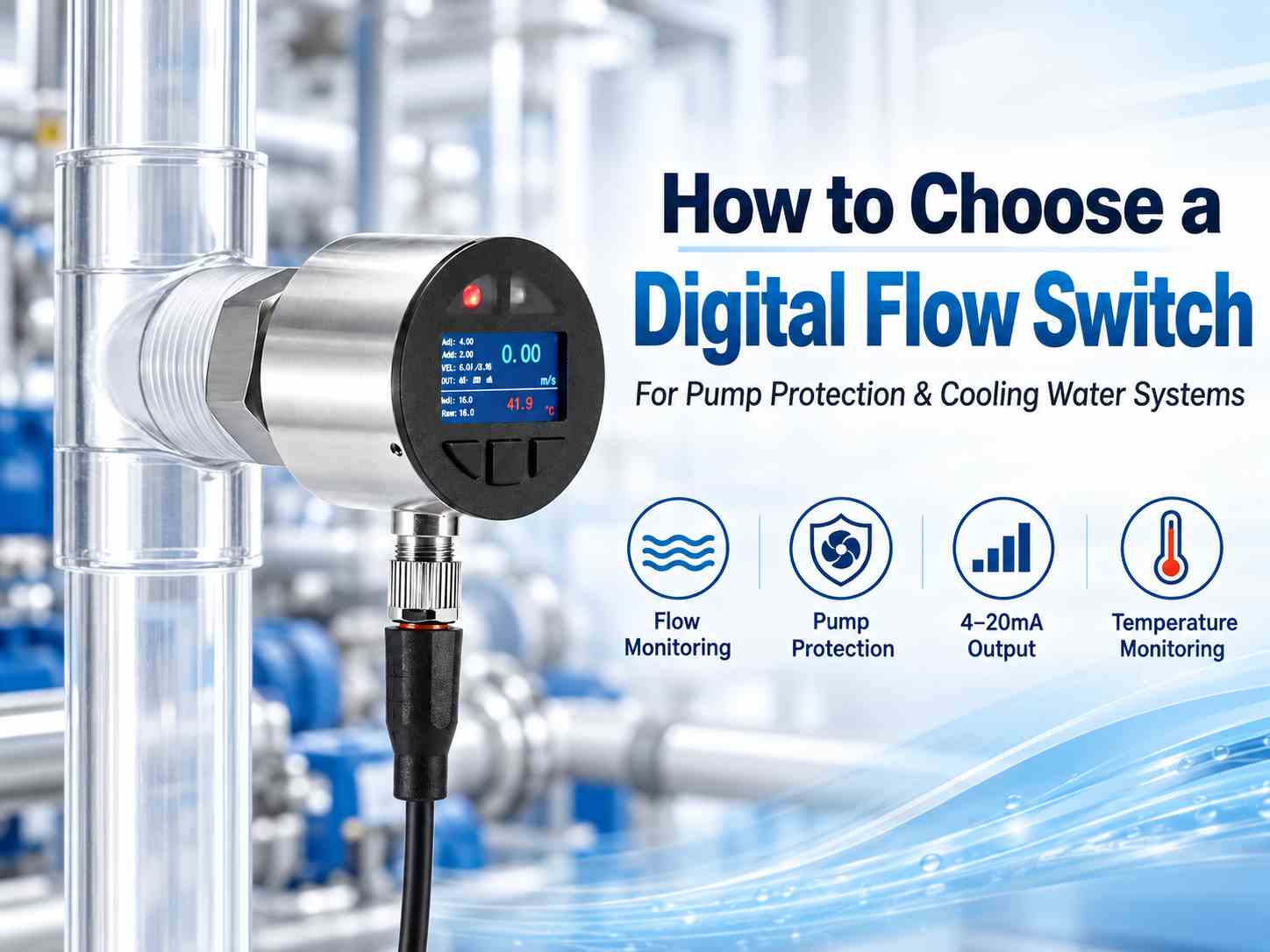
The ZINACA ZNC-DF1 Digital Flow Switch uses this thermal sensing principle and combines flow velocity monitoring with medium temperature measurement in one compact instrument.
Why Is Flow Monitoring Important for Pump Protection?
Pumps are widely used to circulate cooling water, process liquids, and other industrial fluids. However, insufficient flow can result from several operating problems, including blocked pipelines, closed valves, loss of liquid supply, or abnormal pump performance.
If these conditions are not detected, the equipment may continue operating without adequate fluid circulation. A digital flow switch can provide an electronic signal when the measured flow condition crosses a preset threshold.
For example, in a cooling water circulation system:
The pump starts and water begins circulating through the pipeline.
The flow switch monitors the flow condition.
If the measured flow velocity falls below the configured switching point, the switch changes its output state.
The PLC or control circuit receives the signal and activates an alarm or protective action.
This arrangement can help reduce the risk of equipment damage caused by inadequate cooling or insufficient circulation. The flow switch should be integrated into a properly designed control system, with switching thresholds and protective logic determined by the actual application.
Digital Flow Switch Applications in Cooling Water Systems
Cooling water systems are common in industrial machinery, heat exchangers, automated manufacturing equipment, and process cooling installations.
Maintaining sufficient cooling water flow is important because even a relatively small reduction in circulation can affect heat transfer and operating temperatures.
Digital thermal flow switches are suitable for monitoring cooling water conditions where a low-flow indication or electronic control signal is required. Typical applications include:
Industrial water circulation systems
Cooling water pipelines
Heat exchangers and process cooling equipment
Water-cooled manufacturing machinery
Pump protection and flow interlock systems
Industrial automation and monitoring equipment
For applications requiring continuous monitoring, a digital flow switch with 4–20mA output can provide flow velocity information to a PLC or monitoring system. This allows operators to monitor changing flow conditions rather than relying only on a basic flow/no-flow indication.
Why Choose a Digital Flow Switch with 4–20mA Output?
Different industrial control systems require different types of electrical signals.
A conventional flow switch typically provides a switching output that indicates whether the monitored flow condition is above or below a set threshold. A digital flow switch equipped with an analog output can provide additional information about the measured flow condition.
The ZINACA ZNC-DF1 offers two configurable output combinations:
| Configuration | Output Functions |
|---|---|
| 2A + 1S | Flow 4–20mA + Temperature 4–20mA + PNP/NPN Flow Switch |
| 2S + 1A | PNP/NPN Flow Switch + PNP/NPN Temperature Switch + Flow 4–20mA |
The 2A + 1S configuration is suitable for applications requiring simultaneous analog monitoring of flow velocity and temperature, together with a flow switching signal.
The 2S + 1A configuration is useful when separate electronic switching signals are required for flow and temperature, while retaining continuous analog flow monitoring.
Both configurations support adjustable Normally Open (NO) and Normally Closed (NC) switching logic. A configurable switching delay of up to 99 seconds is also available.
These options help system integrators select an appropriate signal arrangement for different PLC and automation applications.
Important: Flow velocity is not the same as volumetric flow rate. The ZNC-DF1 measures flow velocity, and its analog flow output should not automatically be treated as a direct volumetric flow measurement.
Key Factors When Selecting a Digital Flow Switch
Selecting a suitable digital thermal flow switch requires careful consideration of the actual operating conditions.
1. Operating Medium
The first step is to identify the fluid being monitored. Thermal flow switches can be used in suitable water, oil, and gas applications, but their measurement performance depends on the thermal properties of the medium.
For the ZNC-DF1, the specified flow velocity range of 0.00–2.00 m/s applies to water. If the instrument is intended for oil, air, or another medium, the required measurement range and application compatibility should be confirmed before ordering.
2. Flow Velocity and Switching Point
The normal operating flow condition and required switching threshold should be established. In pump protection applications, the switching point is generally selected based on the minimum acceptable circulation condition of the equipment.
The threshold should be low enough to avoid unnecessary alarms during normal operation while providing appropriate detection when flow becomes insufficient.
If only volumetric flow data is available, the pipeline dimensions should also be provided to determine the corresponding average flow velocity.
3. Medium Temperature and Pressure
The flow switch must be suitable for the process temperature and operating pressure. The ZNC-DF1 specifications include:
Medium temperature: 0–100°C
Pressure rating: up to 100 bar
Ambient temperature: −20 to 80°C
The operating conditions and wetted material compatibility should be verified before installation.
4. Electrical Output and Power Supply
The output signal must match the receiving PLC, controller, or monitoring equipment. Before selection, confirm whether the application requires PNP/NPN switching, continuous 4–20mA monitoring, or both.
The ZNC-DF1 operates with a 9–36 VDC power supply and provides configurable switching and analog output combinations.
5. Process Connection and Probe Length
Correct mechanical installation is essential for reliable thermal flow sensing. The ZNC-DF1 offers G1/2 male and female process connection options, with different probe lengths available according to the installation requirements.
The probe must extend sufficiently into the flowing medium to provide representative flow sensing. Probe length should therefore be selected according to the pipe's internal diameter, mounting arrangement, and process conditions.
ZINACA ZNC-DF1 Digital Flow Switch: Technical Overview
The ZNC-DF1 is a compact digital thermal flow switch designed for simultaneous flow velocity and medium temperature monitoring.
It features a 1.47-inch LCD, dual LED status indicators, configurable electronic outputs, and stainless steel construction.
Its single-probe design contains no mechanical moving parts, helping minimize pressure loss and avoid wear associated with mechanical sensing mechanisms.
Main Technical Specifications
| Parameter | Specification |
|---|---|
| Model | ZNC-DF1 |
| Measuring Principle | Thermal / PTC Thermistor |
| Flow Velocity Range | 0.00–2.00 m/s (Water) |
| Flow Accuracy | ≤ ±2.5% F.S. |
| Temperature Range | 0–100°C |
| Temperature Accuracy | ≤ ±1.0% F.S. |
| Display | 1.47-inch LCD |
| Output Signals | PNP/NPN and 4–20mA |
| Power Supply | 9–36 VDC |
| Process Connection | G1/2 Male or Female |
| Pressure Rating | 100 bar |
| Protection Rating | IP65 |
| Housing / Wetted Material | SS304 / SS304 |
| Electrical Connection | M12 Connector or Direct Cable |
The combination of digital indication, electronic switching, and analog signals makes the ZNC-DF1 suitable for integration into industrial monitoring and automation systems.
Installation Considerations for Thermal Flow Switches
Proper installation has a direct influence on measurement performance.
For insertion-type thermal flow switches, the sensor probe should be positioned where it can adequately detect the movement of the process medium.
The ZNC-DF1 installation guide illustrates a DN100 pipe application with a probe insertion depth reaching at least half of the pipe's internal diameter.
The guide also provides vertical and side installation examples, with upstream and downstream straight-pipe sections illustrated for the vertical arrangement.
Before installation, confirm the pipe dimensions, probe insertion depth, process connection, and available mounting space. Installations near valves, elbows, pumps, or other flow disturbances should be evaluated according to the actual piping arrangement.
Digital Thermal Flow Switch vs. Mechanical Flow Switch
Both mechanical and digital thermal flow switches can be used for industrial flow detection, but their operating principles and available functions differ.
| Feature | Digital Thermal Flow Switch | Mechanical Paddle Flow Switch |
|---|---|---|
| Operating Principle | Heat Transfer | Mechanical Paddle Movement |
| Moving Sensing Parts | No | Yes |
| Digital Display | Available | Usually Not Available |
| Analog Output | Available on Suitable Models | Generally Not Available |
| Temperature Monitoring | Available on Suitable Models | Usually Separate |
| Electronic Setpoint Adjustment | Available | Model Dependent |
| Application | Electronic Monitoring and Control | Basic Flow Detection |
Mechanical flow switches remain a practical solution for simple flow/no-flow monitoring. Digital thermal flow switches are particularly useful when the application requires adjustable electronic switching, local indication, or continuous monitoring signals.
The most suitable choice depends on the operating medium, required outputs, installation conditions, and control system design.
Frequently Asked Questions
Can a digital flow switch protect a water pump?
Yes. A digital flow switch can detect insufficient water flow and provide a signal to a PLC or control circuit. The control system can then activate an alarm or stop the pump according to the programmed protection logic.
Can the ZNC-DF1 monitor temperature and flow simultaneously?
Yes. The ZNC-DF1 measures flow velocity and medium temperature simultaneously. Depending on the selected output configuration, it can provide analog monitoring and electronic switching signals for these parameters.
Is a 4–20mA flow switch suitable for PLC systems?
Yes. A compatible 4–20mA input can receive the analog signal, while PNP/NPN inputs can be used for switching functions. The correct wiring and output configuration must be confirmed according to the PLC specifications.
Can the ZNC-DF1 probe length be customized?
Yes. Different probe lengths can be configured according to the pipeline dimensions and installation requirements.
Conclusion
Choosing the right digital flow switch is important for reliable pump protection, cooling water monitoring, and industrial automation.
The operating medium, flow velocity, switching threshold, signal output, pressure, temperature, and installation method should all be considered before selecting an instrument.
The ZINACA ZNC-DF1 Digital Flow Switch combines thermal flow sensing, temperature monitoring, a digital display, and configurable PNP/NPN and 4–20mA outputs in one compact device.
For system integrators, equipment manufacturers, and industrial buyers looking for an electronic flow monitoring solution, the ZNC-DF1 offers flexible configuration options for different process requirements.
Learn more about the product:
ZNC-DF1 Digital Flow Switch – Technical Specifications and Datasheet
Contact ZINACA Instruments
Email: sales@zinacainstruments.com
Website: www.zinacainstruments.com
Contact our team with your operating medium, pipe size, flow conditions, pressure, temperature, required output signals, and probe length for product selection and quotation.
 WhatsApp
 Email
Email
 +8617320288925